|
|
|
|
|
|
by
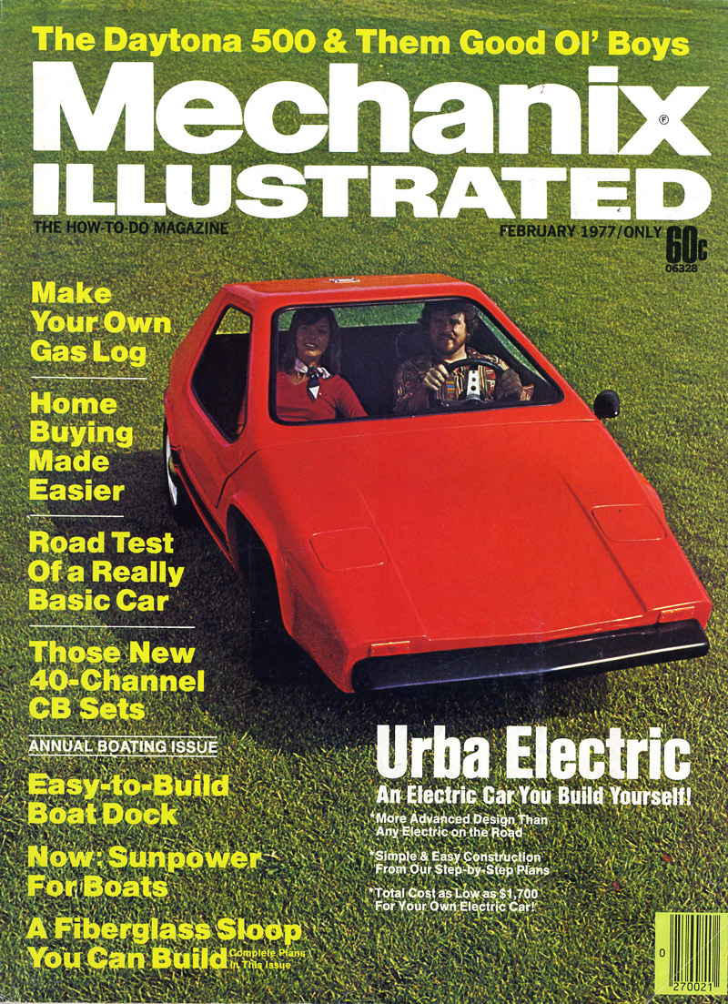
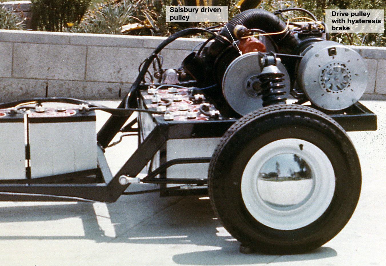
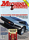
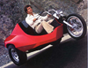
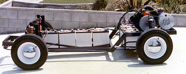
Robert Q. Riley Urba Electric was the first application of the Electromatic Drive in an electric car. And even today, the potential of this transmission in EV application has not been fully explored. In order to understand the signifigance of this first experiment with the Electromatic Drive it helps to mentally roll back the clock to the mid-seventies when the design was developed. Electric cars were not taken seriously by mainstream OEMs, and significant technical problems existed. Hobbyists were building EVs, but most vehicles were simply copies of those that others had built, and little or no real innovation was going on. Batteries were a big part of the problem, and appropriate batteries are just now coming on line. The other major challenge was a smooth, low-cost, and energy-efficient speed control system for high-power electric drives This second challenge is where we focused our efforts in the design of Urba Electric, but it was almost by accident that it happened. Making a Contribution After UrbaCar appeared on the cover of Mechanix Illustrated Magazine, the Editor, Robert G. Beason, asked for a follow-up electric car based on UrbaCar's design. But there was no point in just doing another "me-too" electric vehicle. If it happened, the design would have to make a contribution to the field. That contribution came in the form of a man who came out to see UrbaCar because it had been equipped with one of his continuously variable transmisssions - Foster Salsbury. Foster Foster loved the idea. And he immediately understood the benefits. The drive would be inexpensive, electrical load could be easily monitored and other controls could be brought into play, and it would smoothly control the speed of the vehicle without resorting to a large and costly SCR controller (about $3,000 for an SCR controller, compared to his estimation of $350 for the new CVT). That set the wheels of innovation in motion for the application of the Electromatic Drive Transmission to an electric vehicle, which became "Urba Electric" when it appeared on MI's cover. Electromatic Drive Transmission The Electromatic Drive Transmission was the brainchild of Darrel Hillman. It works just like other continuously variable transmissions (CVT). In fact, the driven pulley on our test-bed was an off-the-shelf “speed-sensitive” (spring loaded) Salsbury driven pulley. Only the drive pulley assembly was specially made. In order to appreciate the innnovation in Urba Electric's power train, you first have to understand how a CVT works. In a conventional snowmobile or ATV type of CVT, the force causing the system to up-shift comes from the centrifigual force of weights in the drive pulley, which force the moveable face toward the fixed face. This causes the belt to ride farther out toward the rim of the drive pulley, which then pulls the belt deeper in toward the center of the driven pulley and results in a change of ratio. Here's an animation showing how it works. The only thing missing in the animation is the force necessary to push the moveable face of the drive pulley toward the fixed face and cause the transmission to up-shift. This video of a real-world CVT made by Team Industries shows how the transmission is also used as a clutch. Notice that at idle the belt is not engaged. But when rpm is increased, the drive pulley squeezes the belt and begins to turn the driven pulley. The Electromatic Drive works like this too. The force necessary for engagement and up-shift is the innovation in the Electromatic Drive Transmission. Consider that the center of the moveable face of the drive pulley is equipped with a ball-nut riding on a lead screw. When the drive pulley and lead screw are spinning in unison, applying a drag to the lead screw will then screw the moveable face toward the fixed face, which causes the system to engage and up-shift. The key is to be able to vary the amount of drag on the lead screw. That is done with a hysteresis brake (a type of magnetic brake) in the drive pulley assembly. The amount of hysteresis braking force is then controlled by a potentiometer mounted on the accelerator pedal inside the cabin. And that, taken together, comprises the core of the system. Up to about 10 mph, the transmission was allowed to slip. At around 10 mph the transmission becomes fully engaged. Above that speed, the speed of the vehicle is controlled by the shift position of the transmission. In a fully up-shifted condition the speed of the vehicle is 60 mph. The compound-wound motor in the prototype (Urba Electric) was set to run at a fixed speed. But in a compound motor, one can also vary the speed of the motor by varying voltage to the low-voltage field windings. This does not require a chopper controller as it would if one were attempting to vary the armature side of the motor. Field current variation can be handled by the internal electronics. Dynamic field variation was not a feature of Urba Electric, but it would have provided greater maximum speed capability. This rubber-belt type of CVT was adequate for Urba Electric. With heavier vehicles, one would have to use a metal belt running in an oil bath. But the principle of operation would be the same. Separately Excited Motor as an Integral Part of the System The test-bed used what's known as a separately excited motor, or one in which the current is applied independently to the field windings and the armature windings. High-voltage primary electrical power was applied to the armature, and a separate but lower voltage was applied to the field, althought both the field and the armature could operate at the same voltage. This type of motor, when energized will run at a fixed speed, and that speed will be determined by the voltage applied to both the armature and the field. By increasing the field voltage, motoring speed will be reduced and by reducing field voltage motoring speed will be increased. "Motoring speed" is the speed at which the motor naturally stabilizes and attempts to maintain. Current drawn by the field windings is much lower than current drawn by armature. So the low-current field excitation may be varied by a simple and inexpensive MOSFET (devices used in today's powered hand drills to vary the speed) in order to change the natural motoring speed. At its natural motoring speed with 48 volts (our system) applied to the armature and 18 volts applied to applied to the field, with no load it demanded only about as much power as a 60 watt light bulb. When the transmission was engaged to propel the vehicle, current to the armature went up, but field current remained the same. And the rpm of the motor was not affected. It remained the same and simply drew more high-power current, as needed to match the load. So during rapid acceleration armature current would see a significant jump while field current remained unaffected, and motoring speed stayed constant. One might say that the motor was naturally operating as an electronic controller would operate. But instead of varying the applied voltage, as is done with an electronic controller, the motor was simply drawing whatever it needed to meet the load placed on it. In a way, the motor was naturally doing what otherwise would have been done using an expensive high-power electronic controller. Other Capabilities Once intelligence and control exist within the system, many other possibilities open up. Urba Electric did not, for example, monitor regeneration current and make adjustments as necessary to maximize regenerative current while holding it within tolerable limits of the battery. Too much regenerative current can damage batteries. But this capability to control current level naturally resides within the system. Current-limiting on the demand side is another built-in capability. Every battery has a natural limit to the maximum tolerable discharge rate, beyond which the battery may become damaged. With the Electromatic Drive, it's possible to monitor high-power current demand and then limit the rate of upshift and/or change field voltage in order to limit load on the battery. Also, due to the effects of field current on motor operating characteristics, minor changes in field current and up-shift position provided the capability of switching into the regeneration/braking mode virtually at any time and any speed. Due to project time and funding limitations, the capability of the system was not fully developed. But even today, with the cost of electronic controllers having dramatically declined, this type of drive is worthy of further experimentation and development. . See Patent Number: US 4174641 A |